Nickel White Gold Welding
12 Minute Read

In this article I will be referring to terms that I have defined in previous articles. If you wish to read those articles in the order that they are meant to be read, contact me at lasers@mantech.info, or 619-239-5842.
Nickel White Gold, (Ni WG), laser welds nicely if some simple steps are taken to overcome challenges that can present themselves for various reasons. What I intend to do, in this article, is identify some problems that can occur and demonstrate some solutions.
We have no choice but to accept some challenges to laser welding jewelry alloys, because we have no control ofhow the piece was previously made, repaired, worn, and treated, even if the piece was one's own creation from start to finish. Characteristics of the alloy have advantages for some purposes and disadvantages for others. Pre-existing conditions (before laser welding, mistaken or deliberate) within the alloy may require us to take some extra precautions before and during laser welding.

A couple of these conditions include the tempered state of the piece, and the actual content of the alloy (depleted or contaminated). Some examples of this are that rapid heating and cooling of the laser weld spot generally result in harder, and consequently more brittle, metal after welding than before welding. Therefore, metal previously hardened from heat-treating or work hardening, greatly increases the welds hardness and brittleness.
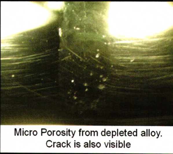
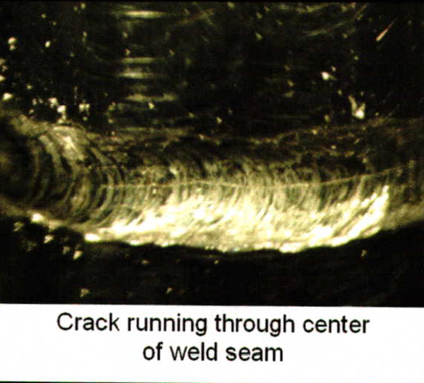
Hard and brittle welds become evident in the metal as a crack appearing like a fault line, forming down the center of the seam and pulling away from the center of the weld spot (not to be confused with a small inward dimple at the center of many weld spots). The micro-cracking appears to vary in extremity, depending on the hardness of the specific material, before and after welding. If the alloy is exposed to too much heat during casting, soldering, brazing, annealing, or laser welding, ingredients of the alloy can be vaporized, burnt, and depleted from of the intended mixture.
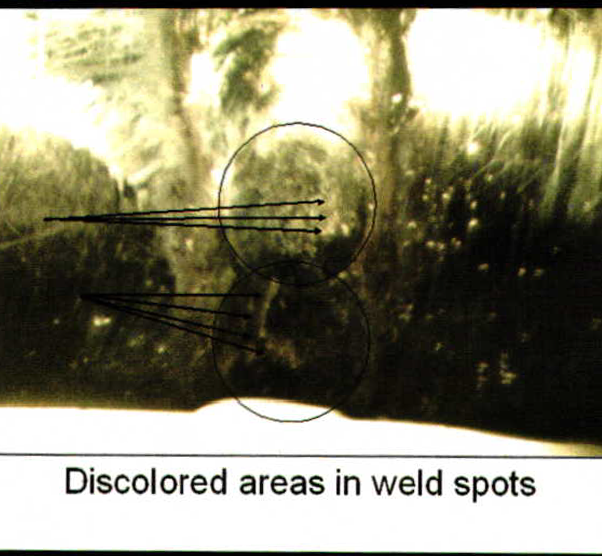
Depletion first becomes evident with discoloration of the alloy while welding. Many alloys of low karatYG will turn blue. The pictured overheated mixture of Ni WG, has reddish brown areas showing in the weld spot. Depending on the pre-existing conditions of the alloy, discolored areas may be unavoidable. However, when discolored areas in the weld spot become visible, precautions should be taken to minimize them.
Further welding, without precautions can quickly lead to various degrees of micro-porosity. Less extreme micro-pours are often not noticed until the finishing, or polishing stages. In more extreme cases they can be noticed as areas on the weld spot that do not congeal together, forming a small crater. Attempts to fill the crater, or melt it back together, are futile and only cause the problem to become worse. One of the most common types of 'contamination' encountered, when laser welding jewelry, has to be from solder. The soldering, or brazing, that we do with a torch flame presents risk of overheating the solder, and in extreme cases, even the parent material being joined, causing depletion.
However, even if a soldered seam or area is not depleted, laser welding could be the culprit to cause, or worsen depletion, if attention is not given to noticing the signs, and the necessary precautions are not taken. Soldered areas have lower melting temperatures, and are softer. Comparing welding on parent material without solder, to welding on the same material that is contaminated with solder will show that the laser will effect the soldered area much more aggressively. The alloy will splash and splatter easier. One can even hear, and sometimes feel the, 'splatter', and difference in the effect. Solders get their lower melting temperature characteristics from a higherzinc, (Zn), content. Zn happens to be the metal that usually vaporizes first.
I have no formal training in metallurgy, but by observing the effects of alloys in various stages of depletion, before and after laser welding; it appears to me that Zn acts like a glue or bonding agent within the mixture helping to hold the other elements together. When the Zn goes away, so does the intended alloy. Depending on the extremity of the depletion, and the desired result of the weld, depleted areas may require being replaced, ifpossible, with new alloy.
Lately, a few jewelers that I have been working with in regards to laser welding, have been using a Ni WG alloy that is very high in Ni content. The desirable effect of these alloys is the fact that they are so white. One laser welding draw back to these alloys is that they are so hard. Some alloys of Ni WG, high in Ni content, are difficult to weld without experiencing micro cracking and depletion. In the case of Ni WG, it appears to me that harder alloys, higher in Ni content, exhibit easier tendencies of depletion as well as cracking. Perhaps these same alloys also have a high Zn content. I can't know this for sure, because companies keep their alloy recipes secret'
Perhaps just the nature of having such a high Ni content causes easier depletion of other metals such as Zn.In any case, I am curious and learning' Some alloys of palladium white gold, (Pd WG) also exhibit hardening and micro cracking tendencies' However, I recently purchased a piece of newly milled Pd WG, 2.5mm thick x 4mm wide sizing stock' I ordered it to have a medium temper. I was hoping to duplicate the same cracking results encountered with other Pd WG alloys. I was quite surprised that this particular alloy, at a medium temper, required comparatively a much higher energy from the laser to show signs of failure than other Pd WG alloys.
Obviously, all alloys are not created equal, and there is room for more research. Everything has its advantages and disadvantages. This is especially evident in Ni WG alloys. One big looming question, in my mind, is whether there are some custom pulse shapes that will allow us to adjust our energy distribution over the pulse duration, so as to give us better results with greater ease. I hope to learn more as I go along.
The new Ni WG that I am working with for this article required quite a lot of laser energy in order to show you pictured effects ofthe failed alloy. This alloy has a lower Ni and Zn content. However, it is not as white as some would desire. Regardless of how this new metal reacts to the laser, I personally like to take extra precautions to weld with less energy, simply because I know that Ni WG is prone to problems if no precautions are taken. Taking precautions to weld with less energy will minimize negative conditions withinthe seam during future welding. One method of welding with less energy involves cutting a relief over the seam as shown in Figure 1.

The purpose of such a relief is to remove resistance to the laser, allowing us to proportion a lower energy for proper penetration and melting into a thinner section of parent material. Less material requires lower energy thus allowing us less risk of causing failure to the alloy. The extremity of pre-existing conditions would dictate how deep a relief one would consider cutting. Cutting a relief also permits us to replace old alloy that is full of undesirable traits for welding, and replace it with new alloy by deposit welding beads within the opening to fill the relief.
For this kind of deposit welding it is important to proportion our energy (volts & duration), and energy spread (beam diameter), so as to fuse the new filler just into the surface of the old parent material. Aggressive penetration and melting, at this step, defeats the purpose of cutting a relief by possible further damage to the parent alloy and stress to the filler material. For very extreme negative conditions in the parent material it can be beneficial to lightly coat the surface of the relief by deposit welding with smaller diameter wire. The smaller wire requires less energy. The goal is to build up a layer of newer material that is not as problematic as the old parent pieces being joined.
When a foundation of newer, less problematic, material has been laid then quite likely one can graduate to a larger diameter wire. The larger wire will allow for faster filling. One should take care not to use too large of a diameter of wire. I personally do not use larger than .010″,(30 gage) wire. I feel that larger diameter wires risk failure because they have larger mass and require more energy to weld. Regarding the wire: I believe it is far more beneficial to use fully annealed wire than wire fresh out of the drawing die.
Remember that the materials hardness is one of those pre-existing conditions that one must contend with. We rarely have control of these conditions within the parent material being joined, but we do have control over those conditions within the wire we use. Drawing the beads for deposit welding can also be accomplished with less energy if one is able to keep the welding angle at optimum. One can learn more about optimum welding angles by reading the article titled, 'Geometry of Laser Welding'. When depositing welding beads it is beneficial to cause the least amount of stress to the surface being covered. This is accomplished by depositing filler evenly, with each laser pulse, over older parent material or previously deposited new material. The laser pulse frequency should be adjusted to the comfort and skill level of the operator, taking care not to over stress areas on the alloy by exposing them too frequently to the energy of the laser.
I was recently working with Greg Morin, a jeweler from Santa Barbara, CA. As Greg and I were discussing the welding ofNi WG, Greg suggested equation when proportioning my energy with the energy spread. I previously lived by the rule that when welding Ni WG I would simply limit my energy by not exceeding 2.0ms of pulse duration. Remember that the pulse duration is the heating effect within the alloy. Too much heat vaporizes and burns low melt temperature metals such as Zn.
Although I that I was not looking at the whole did not need to exceed 2.0ms on the pictured example for this article I likely could have by using the end of the (volts, duration, and beam diameter) formula that is a displayed value on the Rofin machine display as a reference (Rofin is the make of machine I am most familiar with). Greg's way of looking at total energy and energy spread encompasses all parameters that effect the equation.
My previous method only accounts for one part of the equation. The absolute end of the laser parameter equation is the way that the total energy is spread over a given area, and is expressed, (On the Rofin machine display), as Joules per square centimeter, (J/cm2), a selected total energy distributed over a selected amount of area. The displayed J/cm2 can be used as a reference from one part of the welding job to the next.
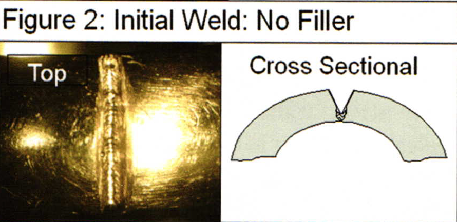
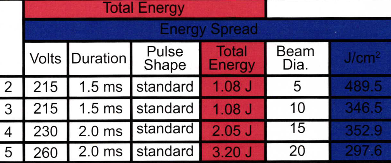
For Example: As shown in Figures 1-5 and the corresponding parameter chart; during initial welding without filler (Figure 2) I chose a beam diameter of 5 because of how the joint fit together, the size of the space I was working in, and the areal wanted to effect. I then proportioned the energy parameters to give the correct penetrating and melting effect necessary for the thickness of material, at the selected beam diameter. Correct proportions of total energy for a given beam diameter involves a setting that does not splash, burn, or crack the weld spot.
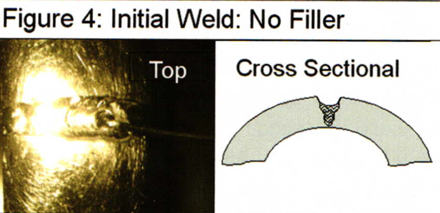
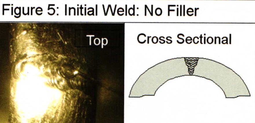
More can be learned about proportioning total energy by reading a previous article titled 'Proportions and Effects'. As wider areas of the relief need to be filled, (Figure 4 and 5), a wider beam is more convenient so as to draw one bead over a larger area, rather than multiple beads over the same area. However, our total energy (Joules) is proportioned to the lowest level to get the job done at a beam diameter of 5. Therefore, widening the beam requires that the total energy be increased by re-proportioning volts and duration for a desired effect with the wider beam diameter.
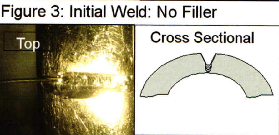
If I wish to affect approximately the same amount of metal with a wider beam as previously effected with a smaller beam, only spreading it in a wider area, thenJ/cm2 can be used as a reference target of a value not to exceed, while re-proportioning the energy. It is important to note that Figures 3-5 did not even come close to the same J/cm2 as Figures 1 & 2 because it was not necessary to adjust the energy higher to get the required results. The displayed J/cm2 is not a target that one must achieve. Rather it is only a reference to help us understand the proportional effects of the three primary welding parameters, volts, duration, and beam diameter.
It also is affected with pulse shaping but I will talk more about that in future articles. On this particular project, I noticed that if I would have used Figure 2 or 3's J/cm2 as a target, rather than a reference, I would have gone too high in total energy and caused failure in the piece. When I teach and train people about laser welding, I try not to let them get too caught up in the displayed parameter numbers. It is much more important to let the desired welding effect determine the numbers, than to let some targeted numbers dictate how the weld is achieved. Using the displayed total energy, (Joules), and displayed J/cm2 helps tremendously to better understand those relationships.
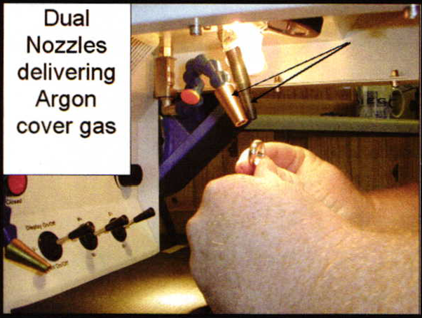
Inert cover gas is very useful when welding Ni WG. Inert gas, (usuallyArgon), does not mix with other elements such as Oxygen. Most machines have a flexible nozzle and a fixed nozzle that are meant to deliver the gas right over the weld spot. The Argon gas pushes Oxygen away, providing an Oxygen free envelope to weld in. I like to use both nozzles, adjusting the flexible nozzle at a slight different angle than the fixed nozzle.
Flowing gas from a slightly different angle is especially useful when welding items to be held by hand, such as jewelry. If a design feature of the piece obstructs flow from one nozzle, cover gas will still be flowing from another nozzle. One should adjust the Argon gas flow so that when one's finger is wet and put on the folac plane, in the crosshairs of the microscope, the finger feels cold. Flow rates that are too high will cause the gas flow to vortex and pull Oxygen back into the envelope.
My last article was about pulse shaping. In that article I said that I would use pulse shaping for welding Ni WG. I'm going to make you wait again until the next article. Until then, best regards to all.
Related Articles:
Pulse Shaping: Energy Over Time
Pulse Shaping: Variable Constants
Pulse Shaping Test, 14k Ni WG
You assume all responsibility and risk for the use of the safety resources available on or through this web page. The International Gem Society LLC does not assume any liability for the materials, information and opinions provided on, or available through, this web page. No advice or information provided by this website shall create any warranty. Reliance on such advice, information or the content of this web page is solely at your own risk, including without limitation any safety guidelines, resources or precautions, or any other information related to safety that may be available on or through this web page. The International Gem Society LLC disclaims any liability for injury, death or damages resulting from the use thereof.
Related Articles
The Secret Life of Solder
Laser Welding Solid Back on Opal Ring
Making Custom-Designed Earrings Using Welding Technology

The New MJSA/WGC White Gold Color Index

The All-In-One Jewelry Making Solution At Your Fingertips
When you join the Ganoksin community, you get the tools you need to take your work to the next level.

Trusted Jewelry Making Information & Techniques
Sign up to receive the latest articles, techniques, and inspirations with our free newsletter.